

This circuit is typical of systems sold for 2.1 PC surround systems, left and right channel and subwoofer. Just plugging in the stereo audio and adjust the volume.
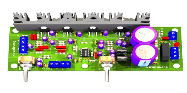
Audio amplifier circuit using integrated TDA2030 and op amp Ne5532, has two stereo amplifier left and right satellite and Bass amplifier using TDA2030 in bridge for more power. The filter is made by double operational amplifier Ne5532. Complete assembly with the suggestion of the printed circuit board and has a power supply coupled to the circuit.
This circuit is a remake of another already posted on the Blog, but with some changes, uses two TDA ic’s in bridge to the subwoofer amp, with a new board design with some improvements. The idea is that to achieve maximum 18Watts satellites and the outputs 32 watts in Subwoofer … This power with a maximum of + -18 Volts Speakers and 4Ω. The circuit has adjustable volume for the stereo and subwoofer. Use pots of good quality to make this work.
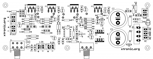
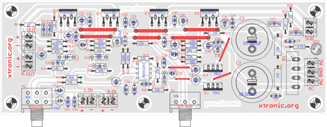
By making the assembly check all connections and all components are correctly positioned, and the orientation of the pcb, be mounted inverted not seen it work, the components have to be positioned as illustrated above. When mounting make sure that the pin 7812 is different from 7912. Use a good heat sink to the TDA IC’s.
The power supply is already fixed in the PCB and only add the transformer, to be with center tap on the secondary and primary according to the network (110/220). The capacitors can be supply of the 4.700μF at 10.000μF, the resistors are in parallel to discharge these capacitors Great. Always use good quality components in its assembly.
The appropriate transformer to the circuit, according to my withdrawal must be at least 3 A transformer or to the 60VA 12-0-12 Volts.
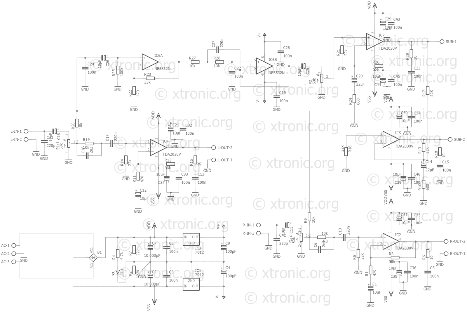
Schematic 2.1 audio Amplifier with TDA2030 in bridge
Suggested Printed Circuit Board 2.1 audio amplifier with Subwoofer Amplifier
List of material for assembly of the power amplifier with subwoofer with TDA2030 and Ne5532
Part / Value
Resistor 1/4W 5%
R1, R11, R22, 470 – Yellow, Violet, Brown, Gold
R2, R7 22k/1W- Red, Red, Orange, Gold
R3, R12, R23, 33k – Orange, Orange, Orange, Gold
R4, R18 4.7k – Yellow, Violet, Red, Gold
R5, R13, R14, R16, R17, R21, R26 22K – Red, Red, Orange, Gold
R6, R15, R19, R20, R29 10 – Brown, Black, Black, Gold
R8, R9 10k – Brown, Black, Orange, Gold
R10, R24 680 – Blue, Green, Brown, Gold
R25, R27, R28 100k – Brown, Black, Yellow, Gold
Capacitors
C1, C7, C11, C12, C18, C21, C25, C26, C29, C30, C31, C37, C38, C39, C44 10µF/25V – Electrolytic Capacitor
C2, C32, C33, C34, C35, C36, C40, C43, C45 4.700µF at 10.000µF/25V – Electrolytic Capacitor
C3, C8, C13, C15, C19, C28 100n (104) – Ceramic capacitor
C4, C9 100µF/25V – Electrolytic Capacitor
C5, C13, C15, C22, C23, C24 100n (104) – Polyester capacitor
C6, C16, C27 2n2 (222) – Polyester capacitor
C10, C17 220n (224) – Polyester capacitor
C14, C20 22µF/25V – Electrolytic Capacitor
C41, C42 220p – Ceramic Capacitor
Semiconductors
B1 KBU8B – Bridge Rectifier – 100V 8A or equivalent.
IC3 7812T – Positive Voltage Regulator +12 V Any prefix (LM, NS, KA, etc.).
IC1 7912T – Negative Voltage Regulator -12V. Any prefix (LM, NS, KA, etc.).
IC2, IC4, IC5, IC7 TDA2030 or TDA2030A – Audio amplifier integrated circuit
IC6 NE5532N – Integrated Circuit Dual Operational Amplifier
LED1 Led 5 mm any color
Conectors
AC 3 Terminals Connector to the transformer
L-IN 2 Terminals Connector left channel audio input
L-OUT 2 Terminals Connector left channel audio output
R-IN 2 Terminals Connector Right channel audio input
R-OUT 2 Terminals Connector Right channel audio Output
SUB 2 Terminals Connector Subwoofer audio output
Miscellaneous
P1 50k – 47K or 50k – Double logarithmic pot, Main Volume Adjustment
P2 50k – 47K or 50k – Single potentiometer – Adjust the subwoofer volume
Soldering, transformer 12 +12 / 4 Amps (50 Va), Wire, Box for Amplifier, PCB, heat sink for the IC TDA, etc..
*See text
Proyecto completo:
Código: Seleccionar todo
https://drive.google.com/uc?export=download&id=19OJR6FP9cvG6Dn8xsPYTqrAg9eORDlvy